How two phase stepper motor with one phase operation works
The purpose of electric motors is to convert electrical energy into mechanical energy. Electric motors come with different size, shape, and working principles. We use the most suitable motor for given application by considering price and efficiency of the motor for the given application. For a job requiring a position control without feedback, a stepper motor is the cheapest and very reliable motor to be considered. All 3D printers, laser cutting machines use stepper motors. A stepper motor converts electrical pulses into specific rotational movements. The movement created by each pulse is precise and repeatable
Stepper motors, just like brushless DC motors are inside out DC motors. By inside out, I mean, inner coils of a DC motor moved to the stator and permanent magnets of DC motor moved from stator to rotor in the stepper motors. While DC motors invented around 18 30, the stepper motor becomes widely available around 19 70. The 150 years after first DC motor is invented. This is because stepper motor or brushless DC motors require complex driving system. While commutator was a good invention for DC motor, stepper motors should wait for 150 years so that integrated circuit and digital technology was available to make complex driving circuits for these new kind motors.
This video animation shows the working principles of the two-phase stepper motor with one phase operation. It is two phase because there are two coil windings for the current to pass. In this video, the vertical coil phase is named as V and the horizontal phase is named as H. It is also called "one phase on operation" because at a given instant the current only pass from Vertical or Horizontal coils but not from both.
To understand the polarity of a coil I use red and blue color for coil windings. The polarity colors are based on the face of coil closest to the rotation center. If coil has red color, this means the face of the coil looking to rotation center has north polarity. Similarly, if a coil has blue color, the face of the coil looking to rotation center has south polarity.
I did not use small yellow circles to show flow direction in some wires to simplify the animation. It is obvious in those cases which direction the flow goes. However, I used the red color to indicate the presence of a current, and brown color as absence of the current.
Let's start to illustrate a typical step sequence for a two-phase motor with starting phase V.
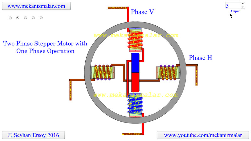
In Step 1 shown above the phase V of a two phase stator is energized. This magnetically locks the rotor in the position shown, since unlike poles attract.
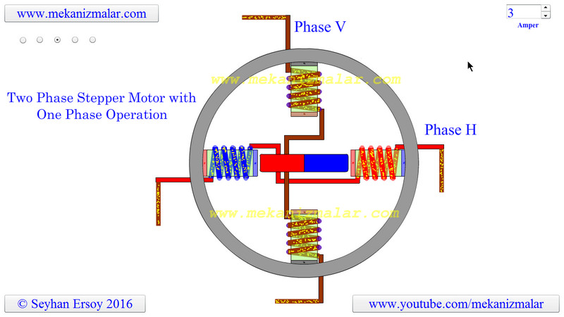
In the step 2 shown above the phase V is turned off and the phase H is turned on, the rotor rotates 90° clockwise.
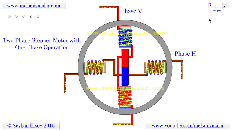
In Step 3 shown above , the phase H is turned off and the phase V is turned on but with the polarity is reversed from Step 1. This means that electric current flows in the opposite direction in step 3 with respect to step 1 current. This causes another 90° rotation during step 3.
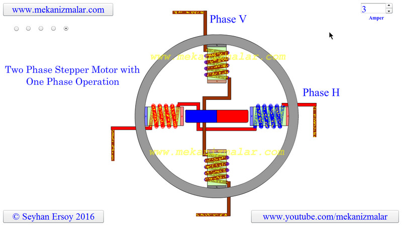
In Step 4 shown above, phase V is turned off and phase H is turned on, with the polarity reversed from Step 2. Repeating this sequence causes the rotor to rotate clockwise in 90° steps.
What is not shown in this animation is that how the direction of currents is changed in the coils. We use H-bridge circuits to accomplish that and it will be the subject of another animation.