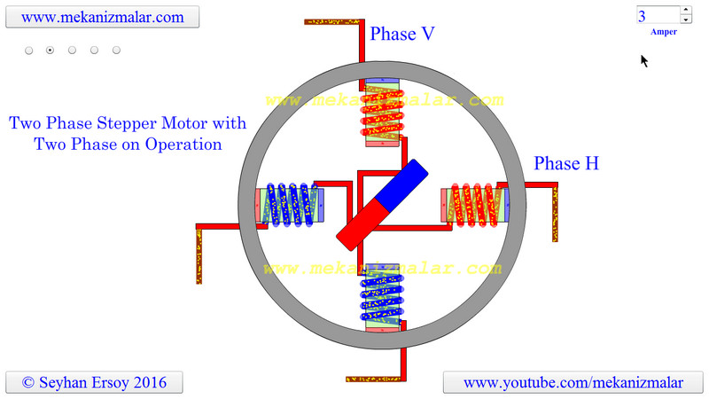
How two phase stepper motor with two phase operation works
In our previous video, we described the working principles of the two-phase stepper motor with one phase on operation.
For this animation, we will show the working principals of the two-phase stepper motor with two phase on operation. It is called two-phase because there are two bipolar coil windings for the current to pass through. For this video, we have named the vertical coil phase V and the horizontal coil phase H. Another reason it is called "two-phase on operation" is that, because at any given instant the current passes through both the Vertical and the Horizontal coils. However, polarity change of bipolar coils is changed alternately. This means that if V phase polarity is changed in a given instant, the next polarity change will be performed during the H phase.
The two-phase on stepper motor uses twice as much power as the one-phase on stepper motor, but produces 41.4 percent more torque in the rotating shaft. The two phase on motor center magnet's north pole aligns itself between two adjacent south pole windings and vice versa.
To distinguish the polarity of a coil I have used red and blue colors for the coil windings. The polarity colors are based on the face of the coil closest to the rotation center. If the coil is red, this means that the face of the coil looking to the rotation center has north polarity. Similarly, if the coil is blue, the face of the coil looking to the rotation center has south polarity.
To simplify the animation, I did not use small yellow circles to show the direction of the flow in some wires. It is obvious in those cases which direction the flow is. However, I used the red color to indicate the presence of a current and the brown color to indicate the absence of current.
Let's start to illustrate a typical step sequence for a two-phase motor with starting phase V.
During step one, the rotor is magnetically locked at the 1.30 hour location on a clock.
During step two, the polarity of V is changed, the rotor rotates 90° clockwise and is locked at the . 3 -hour location.
During step three, the polarity of H is changed, the rotor rotates 90° clockwise and is locked at . 3 -hour location.
During step four, the polarity of V is changed again, the rotor rotates 90° clockwise and is locked at the 1.30 hour location. After that the polarity of H is changed and the cycle is repeats itself.
What is not shown in this animation is that how the direction of currents is changed in the coils. We use H-bridge circuits to accomplish that and it will be the subject of another animation.


